FAMA BUYER’S GUIDE TC045 Multiplex Electrical Systems
Multiplex Electrical Systems
Prepared by the FAMA Electrical Subcommittee
This guide does not endorse any manufacturer or product

Contents
Introduction
This guide is intended to provide fire service personnel with information about the various types of multiplex systems and vehicle data recorders used on fire apparatus. Multiplexing systems integrated into the fire apparatus body are becoming more popular with fire departments and vehicle builders, constituting over 60% of new builds. The primary function of a vehicle multiplex system is to integrate all mission and non-mission critical functions into discrete Input and Output modules for full body control of an apparatus. Secondarily, vehicle data recorders are intended to record and store NFPA 1901 mandated run data for the life of the vehicle.
As multiplex technology is continually evolving, this guide is presented as a general information and educational piece. The various options regarding multiplexing may not be available from every OEM manufacturer, some may be mutually exclusive, or some features may be proprietary to that specific OEM brand.
It is the responsibility of the purchaser to determine what best meets their needs and to specify this information to prospective apparatus bidders, sellers, and manufacturers.
In many cases it is possible to somewhat match your existing apparatus. If your fifteen year old apparatus has rocker switches and your department wants to stay with switches you can do this. If your existing apparatus has a display, you may want to insert some screen layouts in your new apparatus specification.
Definition of Multiplexing:
Being or relating to a system of transmitting several messages or signals simultaneously on the same circuit or channel. In the case of fire apparatus, this same circuit or channel would be a Controller Area Network (CAN). The engines and transmissions run a “flavor” of CAN defined by SAE as J1939. There are many “flavors” of CAN and most of the multiplex systems available today run on CAN.
Overview
This guide will look at various types of multiplex components and vehicle recording devices that are available to the industry on fire apparatus. This guide does not cover electrical components outside of multiplexing, including auxiliary input devices or 3rd party sensors. The review will be provided for (4) different types of multiplex components including:
- I/O Nodes (also called modules)
- User Interface / Display Nodes
- Accessories and Components
- Vehicle Data Recorders
I/O Nodes
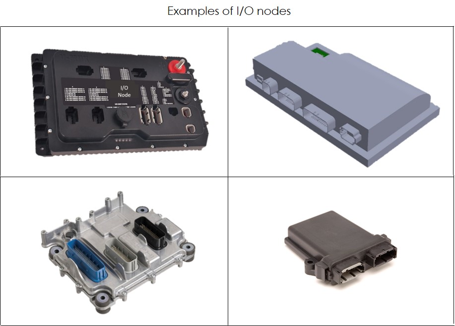
The most basic unit of multiplex system starts with I/O nodes for body and chassis control. I/O nodes can control both the human inputs (buttons, switches) as well as control various outputs on the apparatus, including, but not limited to, lighting, climate fans, ladder racks, interlocks, high idle control, and voltage monitoring.
The core mission of the I/O node is to distribute power with software based logic. This helps to reduce wire harness bundles and electrical control hardware required inside an apparatus. Multiplexing allows carrying of multiple signals over a common line (network), allowing for a more seamless vehicle integration.
Multiplex I/O nodes typically are offered in (2) type of functions: Peer to Peer nodes, or Master / Slave nodes. In a Master / Slave environment, the Master module take in all input and network message requests, processes them, and distributes the proper message to the corresponding output on the Slave node. Peer to Peer multiplex systems offered distributed independent I/O nodes capable of sending network messages to other I/O nodes or by individually controlling outputs directly tied to them. There is no advantage to either approach, but considerations about functionality, control, and design should be understood with your vehicle builder when selecting a system.
As a general guidance, any I/O module should offer these capabilities:
- IP67 rated protection
- Operating temperatures from -40° to +85°C
- 12V and 24V capable
- Corrosion proof
- Hardware designed to meet the testing intentions of SAE J1455
User Interface / Display Nodes
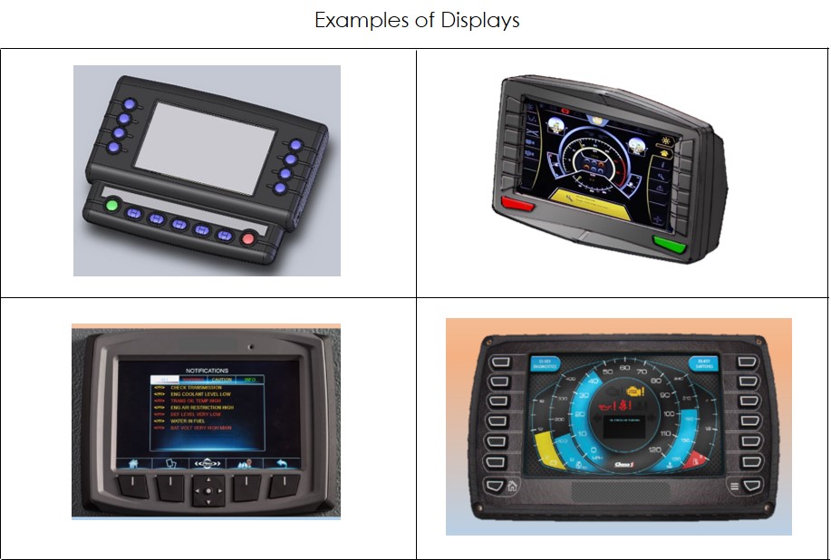
The function of user interface / displays is to centralize common multiplex functions into 1 common display, typically mounted inside the vehicle on a swivel or arm mount. Displays can range in size or function, with some containing physical buttons and some offering both physical button and touch capabilities and some with touch only features. Common functions like warning lights, A/C control, diagnostics, emergency lights, audible alarms, PTO engagement, engine and chassis performance, and other common apparatus functions are displayed on the display.
Many OEM builders can utilize design software to create a user experience for the end user to match specific functions and control demands of the apparatus. Many common displays today contain the following features:
- Fully sealed and weatherproof to IP67
- Video feed capable: navigation or video feeds
- Accept reverse or front facing cameras
- 800 NIT or higher display brightness
- 12V and 24V capable
- -40° to +85°C operating temperature
- Tested to SAE1455 standards
- Field reprogrammable
Accessories and Components
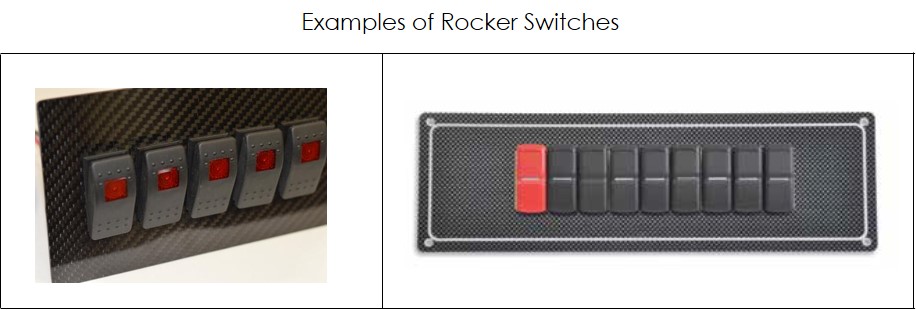
In addition to in vehicle UI displays, a number of different input options exist with multiplex systems to enhance the look or functionality inside the apparatus. These could include, but not be limited to:
- Rocker Switches
- Programmable Soft Touch Buttons
- Information Displays
- Rotary Joysticks
The key enabler of these input devices is that builders of apparatus can include combinations of these devices to provide an intuitive yet custom experience for your department’s needs. Typical installations connect multiple input devices along with I/O nodes, simplifying wiring, making troubleshooting easier. Input devices such as switches and displays are typically CAN based.
Some common requirements of Input Accessories include, but not limited to:
- Fully sealed and weatherproof to IP67
- 12V and 24V capable
- -40° to +85°C operating temperature
- Tested to SAE1455 standards
Vehicle Data Recorders
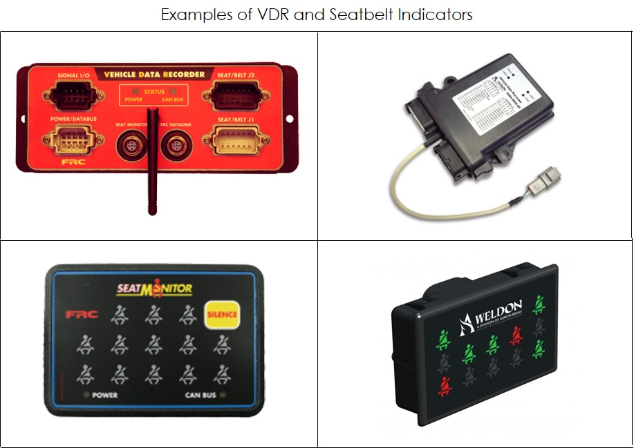
In 2009 it became a requirement under NFPA-1901for each fire apparatus to contain a vehicle data recorder. The function of vehicle data recorders is to keep a second-by-second record of the vehicle speed, acceleration and deceleration, engine speed, throttle position, anti-lock braking system events, master warning light switch position, date and time inside the apparatus. It also keeps a minute-by-minute summary of this data on a running 100-engine hour loop. NFPA 1901 also mandates recording of Six (6) seat position inputs for occupied Seats and belts buckled. Many Vehicle data recorders also provide additional six (6) seat expansion modules for further seat belt recording.
In addition, NFPA 1901 also requires a seat monitor visual display that shows the condition of each seating position. The system recognizes the correct sit-buckle sequence and provides 2 outputs for audible alarms. All seating positions are designed to be occupied while the vehicle is in motion and a visual display visible to the driver or the officer showing the condition of each seating position. The audible warning shall be activated anytime the parking brake is released or the automatic transmission is not in park. These systems can off load the data via USB or some have optional wireless offload options.
